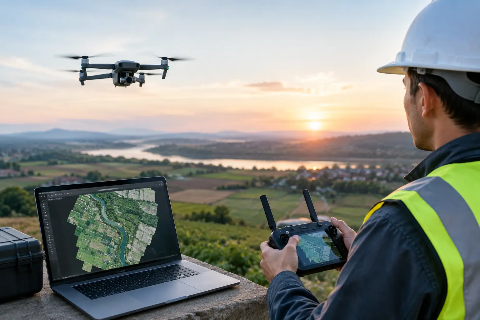

A drone map can look perfectly aligned on screen and still be unsuitable for measurement. A curb may appear straight, roof edges may line up, and the colors may be excellent, yet the entire orthomosaic can be shifted by several feet. For teams using aerial data to plan works, document progress, assess assets, or communicate with stakeholders, drone orthomosaic accuracy is not a visual preference. It determines whether the map can support a defensible decision.
The right accuracy standard depends on the job. A property marketing overview does not require the same controls as earthwork verification, boundary-adjacent planning, or an as-built comparison. The key is defining the required tolerance before the aircraft takes off, then designing the capture and processing workflow around it.
What an orthomosaic actually measures
An orthomosaic is a geometrically corrected aerial image assembled from many overlapping photographs. Processing software identifies common features across images, reconstructs camera positions, models the terrain or surface, and projects the imagery into a single map view. Unlike a standard aerial photograph, an orthomosaic is corrected for camera perspective and, where the source model is reliable, terrain displacement.
That process makes measurement possible, but it does not make every pixel equally accurate. Accuracy is affected by the drone’s position, image quality, the geometry of the flight, the surface being mapped, survey control, and the processing choices made afterward. A high-resolution image can be highly detailed while still being poorly located in the real world.
This distinction matters for commercial projects. A developer may need a clear site overview for a sales presentation, while a contractor may need map coordinates that align with a survey grid and existing BIM or CAD data. Both need an orthomosaic, but they need different levels of positional confidence.
Drone orthomosaic accuracy starts with a clear standard
Accuracy is commonly discussed in two forms: relative and absolute. Relative accuracy describes how well features align with each other within the map. For example, the distance between two drainage structures may be consistent even if the whole map is offset. Absolute accuracy describes how closely those features align with their true coordinates in the required coordinate reference system.
A visually convincing map can have strong relative accuracy and weak absolute accuracy. This is why a map captured using only standard drone GPS may be useful for progress visuals but unsuitable for dimensional coordination with survey data.
Before commissioning a flight, identify the business decision the map must support. Is the output for site communication, land area estimation, construction progress, preliminary design, stockpile analysis, or evidence of existing conditions? What units, coordinate system, vertical datum, and tolerance does the client team use? These questions prevent an expensive mismatch between a polished deliverable and an operational requirement.
Ground sampling distance, or GSD, should also be treated carefully. GSD indicates the real-world size represented by one pixel. A 1-inch GSD can reveal fine surface detail, but it does not guarantee 1-inch positional accuracy. As a practical rule, achievable horizontal accuracy is often several times the GSD, subject to control quality, flight geometry, and processing. Promising accuracy from GSD alone is a common and avoidable error.
Control points, RTK, and PPK serve different roles
Reliable absolute accuracy begins with reliable reference data. Ground control points, or GCPs, are clearly marked targets placed across the site and measured with survey-grade methods. During processing, they anchor the model to known coordinates. Their value is not simply their presence. Their distribution, measurement quality, visibility in imagery, and relationship to the site’s coordinate system all matter.
Control points should cover the full survey area rather than being concentrated near the takeoff location or site access road. A practical arrangement includes points around the perimeter and within the interior, with attention to elevation changes and complex zones. A long, narrow corridor, a steep site, or an area with retaining walls may require a more deliberate layout than a flat, open parcel.
RTK and PPK drones improve the geotagging of each image by using corrected satellite positioning. RTK applies corrections during flight, while PPK applies them after capture. Both can substantially improve efficiency and reduce the number of GCPs required on accessible sites. They do not eliminate the need for independent validation.
Checkpoints provide that validation. Unlike GCPs, checkpoints are surveyed positions that are withheld from the processing adjustment. Comparing their known coordinates with their mapped coordinates provides an independent measure of error. For engineering, construction, insurance, and asset-management use cases, checkpoints are often the clearest way to demonstrate that a stated accuracy target was achieved.
Flight planning determines whether processing has enough evidence
Orthomosaic processing depends on seeing the same ground features from enough useful angles. Flight altitude, image overlap, camera angle, speed, and exposure settings shape that evidence.
Higher overlap generally gives the software more image matches and can improve reconstruction in complex areas, but it also increases flight time, image volume, processing time, and cost. A simple, flat site may perform well with a conventional nadir flight, while dense industrial facilities, roof structures, cut-and-fill areas, and facades may require more overlap and oblique imagery.
Motion blur is another quiet source of error. Flying too fast in low light can soften imagery, weaken tie-point matching, and create distorted edges. Wind can introduce similar issues, especially when mapping tall structures or vegetation. Consistent light helps too. Hard shadows can obscure ground targets, while reflective roofs, water, glass, and uniform surfaces such as fresh asphalt provide few stable visual features for image matching.
Vegetation introduces a separate limitation. An optical orthomosaic records the top visible surface, not necessarily the ground beneath it. In a landscaped property or plantation area, the map may accurately represent canopy but not terrain. Where bare-earth elevation is needed below vegetation, LiDAR may be the more appropriate capture method, often combined with drone imagery for a readable visual layer.
Processing choices can shift the final map
The processing stage is not a push-button exercise when accuracy matters. Camera calibration, image alignment thresholds, outlier removal, dense reconstruction settings, control-point marking, and coordinate transformations all influence the output.
Coordinate reference systems deserve particular attention in Malaysia, Singapore, Indonesia, Thailand, and other regional projects where client datasets may use local grids, projected systems, or distinct vertical references. A map can be internally correct but misaligned with a design model if the wrong coordinate system, datum, or geoid model is applied. This is especially consequential when drone deliverables are compared with LiDAR scans, Scan-to-BIM outputs, utility surveys, or construction layout data.
Elevation requires the same discipline. A drone-derived surface model may report heights relative to an ellipsoid, a local benchmark, or a national vertical datum depending on the workflow. These are not interchangeable. Teams should confirm the vertical reference before calculating volumes, checking drainage slopes, or comparing construction progress across different survey dates.
Quality assurance should include more than reviewing the map at a convenient zoom level. Look for seamlines through moving vehicles, warped building edges, ghosting around trees, gaps in image coverage, and unexpected shifts along the perimeter. Then review checkpoint residuals and document the reported horizontal and vertical error in the final deliverable. That record gives project teams confidence in what the data can, and cannot, support.
Matching accuracy to commercial value
The most accurate workflow is not always the most valuable one. Survey-grade control requires field access, coordination, equipment, and time. More overlap and oblique capture increase processing demand. LiDAR adds capability in complex terrain or vegetation but may not be justified for a straightforward visual site map.
The better question is whether the accuracy level reduces a meaningful project risk or improves a decision. For a resort operator documenting property assets across a large site, a controlled orthomosaic can create a common visual reference for maintenance planning and vendor coordination. For a developer, it can support clear progress reporting for remote investors. For an AEC team, it can become a dependable layer alongside BIM, LiDAR, and survey information when control and validation are designed correctly.
Novo Reperio approaches aerial mapping as part of a wider spatial data strategy, not as a standalone drone flight. When orthomosaics must connect with digital twins, 3D models, as-built documentation, or operational records, the capture specification should reflect the full workflow from the outset.
A practical acceptance checklist
Before accepting an orthomosaic for measurement or coordination, confirm four things: the intended use and tolerance were agreed in advance; the coordinate and vertical reference systems are documented; survey control and independent checkpoints were used where the risk justifies them; and the final report states measured error rather than relying on a claimed camera or drone specification.
That discipline changes the conversation from “How sharp is the image?” to “Can our team rely on this spatial data?” For organizations managing complex sites, that is the measure that turns aerial imagery into a decision-making asset.